|
To balance a V-8 engine requires 50% of reciprocating weight
plus 100% of rotating weight, for a V-8 engine.
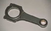
Reciprocating weight: Piston (1), rings (1 set), wrist
pin (1), and small end of connecting rod (1).
Rotating weight: Big end of connecting rod, rod bolts
& nuts, rod bearings, & oil supply to crankshaft bearings.
Because there are two rods to each journal then the rotating
weight is x 2.
The pistons are all machined to weigh the same. The big end of
connecting rods and small end of connecting rod are machined
to weight the same (separately). Then the weights of the pistons,
big end of connecting rods, small end of connecting rod, one
set of rod bearings, one set of rings, one wrist pins and oil
weight (usually 6 grams) is recorded and the bob weights are
made up from the formula for the type of crankshaft being balanced.
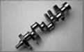
Then the bob weights (4 for a V8), dampener, flywheel (flex plate)
are bolted to the crankshaft and spun to balance the left side
and the right side of the crankshaft. Then spun with the left
side and right side coupled together to make sure the crankshaft
is still in balance.
The crankshaft is either welded on the counter weights (or heavy
metal installed) or drilled on the counter weights (left and
right) to bring the crankshaft into balance.
All four cylinder engines (inline) and inline 6 cylinder crankshafts
(with the counter weights on the same side) do not require bob
weights.
V6 crankshafts, because the counter weights are on opposite sides
require bob weights but some formulas are different for each
V6.
Blueprinting
To blueprint an engine consists of several machine shop operations
including but not limited to:
Bore & hone cylinders (usually w/Deck plates) and honed
to the correct clearance.
Line bore or line hone the main housing bore in the block.
(Or at least check to see if the housing bore is within the correct
specifications).
Re-size connecting rods (big end & sometimes small end).
Turn & Index crankshaft.
3 angle valve job cylinder heads (to a specific width &
place on valve seat & valve face).
Fitting valve guides to a specific clearance.
Setting up valve springs to the right installed height &
pressure, both open & closed.
Surfacing block and cylinder heads straight & with the
right RMS finish.
Race engines require even more blueprinting----such as; cc'ing
heads, machining for exact deck, block clearancing for crankshaft,
& cam to rod clearance, porting & polishing, shot peening,
heat treating,---the list goes on & on.
Crankshaft Installation Guide
1. IDENTIFY MATCHED PARTS:
Before engine disassembly, all connecting rods and matching caps
should be numbered according to cylinder location. Each main
bearing cap should be numbered according to it's location in
the block.
2. CHECK CONNECTING ROD HOUSING BORES:
Connecting rod housing bores must be checked for roundness and
size using bore gauges or inside micrometers. If the housing
bore does not meet specifications, it should be reconditioned
by a qualified machine shop.
3. CHECK MAIN BEARING BORES:
With the engine block inverted, main bearing bores must be checked
for alignment and size. If necessary, engine block should be
reconditioned by a qualified machine shop before reuse.
4. CLEAN OIL PASSAGES IN CRANKSHAFT:
Ensure that oil ways and holes are cleaned using a brush and
compressed air. When using compressed air, be careful not to
blow dirt onto previously cleaned surfaces
5. CLEAN OIL PASSAGES IN ENGINE:
Thoroughly clean oil ways using compressed air and a brush. Be
careful not to blow dirt onto previously cleaned surfaces
6. CLEAN MAIN BEARINGS AND BORES:
Bearings and main bearing bores must be cleaned and dry.
7. CHECK OIL HOLE ALIGNMENT:
Ensure bearing locating tang lines up exactly with recess in
block and that oil feed hole lines up with hole or slot in bearing
to ensure proper oil flow.
8. LUBRICATE BEARING SURFACES :
Lubricate all bearing surfaces and rear lip seal with clean engine
oil. We do not recommend the use of greases for this purpose.
9. CRANKSHAFT INSTALLATION:
Gently and squarely place the crankshaft onto the main bearings.
Care should be taken to prevent damage to the bearing flange
thrust surfaces. Main caps and bearings must then be installed
in proper positions.
10. TORQUE MAIN BEARING BOLTS:
All bolt threads must be cleaned and lightly lubricated to obtain
correct torque readings. Final tightening of all bolts must be
in accordance with engine manufacturer's specifications. Crankshaft
should rotate freely after tightening procedure. Check for proper
oil clearance prior to final assembly of main bearings.
11. CONNECTING ROD INSTALLATION:
Before installing piston and rod assemblies, rod bolt threads
must be covered to prevent damage to crankshaft journals.
12. ROD CAP INSTALLATION:
Match rod caps in accordance with cylinder numbers on connecting
rods. Check for proper oil clearance prior to final assembly
of the rod bearings. Torque rod bolts or nuts to manufacturer's
specifications.
13. CHECK PROPER END CLEARANCE:
By using a feeler gauge, check for proper end clearance between
crankshaft thrust and bearing flange to manufacturer's recommendations.
14. PRIME ENGINE OILING SYSTEM:
Before starting engine, oiling system must be primed to prevent
dry start and damage to bearing surfaces |